In its simplest form, the sensor operates as an analogue transducer, directly returning a voltage. With a known magnetic field, its distance from the Hall plate can be determined. Using groups of sensors, the relative position of the magnet can be deduced.
Electricity carried through a conductor will produce a magnetic field that varies with current, and a Hall sensor can be used to measure the current without interrupting the circuit. Typically, the sensor is integrated with a wound core or permanent magnet that surrounds the conductor to be measured.
Frequently, a Hall sensor is combined with circuitry that allows the device to act in a digital (on/off) mode, and may be called a switch in this configuration. Commonly seen in industrial applications such as the pictured pneumatic cylinder, they are also used in consumer equipment; for example some computer printers use them to detect missing paper and open covers. When high reliability is required, they are used in keyboards.

Hall sensors are commonly used to time the speed of wheels and shafts, such as for internal combustion engine ignition timing, tachometers and anti-lock braking systems.
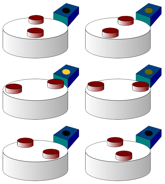
They are used in brushless DC electric motors to detect the position of the permanent magnet. In the pictured wheel carrying two equally spaced magnets, the voltage from the sensor will peak twice for each revolution. This arrangement is commonly used to regulate the speed of disc drives.
Hall Probe
A hall probe contains an indium compound crystal such as indium antimonide, mounted on an aluminum backing plate, and encapsulated in the probe head. The plane of the crystal is perpendicular to the probe handle. Connecting leads from the crystal are brought down through the handle to the circuit box.
When the Hall Probe is held so that the magnetic field lines are passing at right angles through the sensor of the probe, the meter gives a reading of the value of magnetic flux density (B). A current is passed through the crystal which, when placed in a magnetic field has a "Hall Effect" voltage developed across it. The Hall Effect is seen when a conductor is passed through a uniform magnetic field. The natural electron drift of the charge carriers causes the magnetic field to apply a Lorentz force (the force exerted on a charged particle in an electromagnetic field) to these charge carriers. The result is what is seen as a charge separation, with a build up of either positive or negative charges on the bottom or on the top of the plate. The crystal measures 5 mm square. The probe handle, being made of a non-ferrous material, has no disturbing effect on the field.
A Hall Probe is sensitive enough to measure the Earth's magnetic field. It must be held so that the Earth's field lines are passing directly through it. It is then rotated quickly so the field lines pass through the sensor in the opposite direction. The change in the flux density reading is double the Earth's magnetic flux density. A hall probe must first be calibrated against a known value of magnetic field strength. For a solenoid the hall probe is placed in the center.
Hall Effect Sensor Interface
Hall effect sensor may require analog circuitry to be interfaced to microprocessors. These interfaces may include input diagnostics, fault protection for transient conditions and short/open circuit detection. It may also provide and monitor the current to the hall effect sensor itself. There are precision IC products available to handle these features. For example the Hall Effect Interface IC from Maxim Integrated Products is MAX9921.
Motor On A Hall Effect Switch

This is a simple and probably the most reliable motor. You may take a look at how easy it is to assemble this motor from the kit.
In 1879 Edward Hall placed a thin layer of gold in a strong magnetic field. He connected a battery to the opposite sides of this film and measured the current flowing through it. He discovered that a small voltage appeared across this film. This voltage was proportional to the strength of magnetic field multiplied by the current. This effect bears his name.
For many years the Hall effect was not used in practical applications because the generated voltage in the gold film was extremely low. However, in the second half of the 20th century the mass production of semiconductor chips started. Chips based on the Hall effect became inexpensive and widely available.
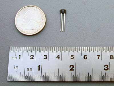
The Hall effect IC (integrated circuit) is a very small chip which includes many transistors. It consists of a thin layer of silicon as a Hall generator (which works better than gold) and several transistor circuits: to amplify the Hall voltage to a necessary level; to trigger output voltage with its growth; and to provide stable work regardless of the power supply voltage changes. The picture below demonstrates the Hall effect IC:

The Hall effect IC used in Kits 6 and 8 (or available as a separate part) is a unipolar switch. It turns on and off when the South pole of the magnet passes by its branded side. The North pole has no effect on it, unless it approaches from the back side of the Hall IC. This Hall effect IC has a built in voltage regulator and may work in the range from 4.5 to 24V. The Hall effect IC's included in the kit, however, were tested extensively; and it was found that most of them start working at 3V. This is a typical Hall effect IC shown from the branded side:

The Hall effect switch output current is not sufficient to power this motor, therefore it also requires a power transistor. You may find information on this component at How It Works: Reed Switch Motor With A Transistor.
This is how this motor works:
1. When magnet #1 gets close to the Hall IC, the sensor sends a signal to the base of the power transistor.
The transistor opens, and allows a bigger collector current to flow through the electromagnet. The electromagnet pushes magnet #3 away.

This disables the electromagnet.

3. The rotor continues to spin due to inertia until magnet #2 moves into the working range of the Hall IC. The Hall IC sends a signal to the base of the transistor.
The transistor opens, and allows a bigger collector current to flow through the electromagnet. The electromagnet pushes magnet #4 away.
This process continues until the power is disconnected.

This motor can be built from Kit #6. Complete instructions are provided. However, if you decide to design this motor yourself, you may order only the parts you need (Hall effect IC, PNP power transistor, magnet wire, magnets, heat sink).
Our experiments showed that the speed of this motor could be controlled by an extra magnet the same way the speed control unit works for the reed switch motors (see Assembly Instructions: Experimentation Kit #1 and How It Works: Reed Switch Motor). The magnetic field of the additional magnet placed near the Hall effect IC interacts with the magnetic field of the magnets on the rotor. As you move this additional magnet the combined magnetic field becomes stronger or weaker depending on the orientation of the speed control magnet. It affects the time the Hall sensor sends the signal to the transistor and therefore changes the motor speed. You may buy a speed control unit or just an additional magnet at our ordering page.
Fuente: http://en.wikipedia.org/wiki/Hall_probe#Hall_probe, http://www.simplemotor.com/hemotor.htm
Nombre: Rodriguez B. Joiver I.
Asignatura: CRF
Get news, entertainment and everything you care about at Live.com. Check it out!
No hay comentarios:
Publicar un comentario