Mostrando entradas con la etiqueta II 2010-1 CRF Rodriguez B. Joiver I.. Mostrar todas las entradas

domingo, 27 de junio de 2010

Observation of the Spin Hall Effect of Light

Physicists Onur Hosten and Paul G. Kwiat, at the University of Illinois at Urbana-Champaign showed that light exhibits a Spin Hall effect, analogous to the Spin Hall effect in electronic systems, showing the universality of the effect for particles of different nature. The researchers used a novel technique from quantum weak measurements to enhance the tiny Spin Hall displacements prior to observation.

Hosten-Kwait


Whenever the propagation direction of a beam of light changes due to a variation in the refractive index of the medium (in the experiment, refraction at an air-glass interface serves this purpose), the beam center experiences a spin-dependent (or circular polarization-dependent) displacement perpendicular both to the initial propagation direction and the change in the propagation direction, i.e. a lateral shift. Two different spin components (parallel and anti-parallel to the propagation direction) acquire opposite displacements. This is the spin Hall effect as it applies to light. Therefore, when a beam of linearly polarized light (which is an equal combination of spin parallel and anti-parallel to the propagation direction) changes direction, the beam slightly splits into two beams, each containing different spin states.

[1152697animation.gif] 
Figure 1: Spin Hall Effect of Light

In the animation, a beam of linearly polarized light incident on an air-glass interface slightly splits into its two spin components -- spin parallel or anti-parallel to the propagation direction (or right and left circular polarizations) -- upon refraction at the interface.

The effect takes place due to conservation of angular momentum (spin plus orbital). Due to the rotational symmetry around the axis perpendicular to the interface (z-axis), the total angular momentum of light around this axis has to be conserved. Assume that, initially the spin angular momentum of light is either parallel or anti-parallel to the propagation direction, and has a certain component along the z-axis. When light refracts at the interface, the spin still remains either parallel or anti-parallel to the new propagation direction. But this time the spin makes a different angle with the z-axis, therefore the spin angular momentum component along the z-axis changes. The spin Hall effect compensates for this change in the angular momentum component, and light acquires an orbital angular momentum by shifting itself laterally from the z-axis.

In the experiment a linearly polarized laser beam was incident on a glass prism at an angle. Upon refraction, the two different spin components acquired opposite displacements out of the plane of incidence. Because the separation between these two beams was only on the order of nanometers, and the beam widths themselves on the order of millimeters, the two beams overlap to a great extent. The researchers measured the separation between the two beams using a novel metrological method (quantum weak measurements in pre- and post-selected systems) to measure the miniscule effect.

Essentially, the spin Hall effect performs a weak measurement of the spin state of the photons. If the measurement were to be strong, the beams corresponding to different spin states would completely separate from each other, and one would be able to tell the spin state by looking at the beam position. But, in the University of Illinois experiment, the spin state measurement was a weak measurement, because the beams were still overlapping to a great extent and one could tell only very little about the spin state by looking at the position of the beam.

When the researchers made a particular pre- and post-selection on the polarization state of the photons before and after the weak measurement (i.e., the spin Hall effect), due to an interference effect between the two beams, there resulted an enhancement of the original displacement by a factor of ten thousand. This pre- and post-selection step experimentally amounts to sending the photons through two calcite polarizers, one before and one after the spin Hall effect, oriented at angles almost perpendicular to each other. Therefore, for instance, an angstrom displacement was enhanced to a micron displacement. Then the enhanced displacement was read by a position-sensitive photodiode (a photodiode split into two halves – the difference signal is proportional to the beam displacement). The researchers were thus able to characterize the Spin Hall effect of light with angstrom resolution.

The measurement technique holds further promise for achieving better resolutions. In particular, the researchers believe that by incorporating standard signal modulation and lock-in detection techniques, a resolution of picometers can be achieved. Moreover, the technique is not limited to position measurements; similar tricks in the appropriate experimental conditions will enhance any kind of signal, e.g., position or momentum of any particle, intensity (e.g. photon number) or amplitude (e.g. electric field) of a field.

The researchers think that it would be interesting to demonstrate the case when the index of refraction varies continuously (as opposed to observing the effect at a discrete air-glass interface), which is the analogous case for the spin Hall effect in semiconductors. The researchers are also theoretically looking for systems where they can separate the spin states into two completely separate beams, and use this for both quantum and classical optical information processing applications.


Fuente: http://www.2physics.com/2008/02/observation-of-spin-hall-effect-of.html
Nombre: Rodriguez B. Joiver I.
Asignatura: CRF


Explore the seven wonders of the world Learn more!

Differential Hall Effect Sensors Aid Rotational Speed Control

A multitude of devices, vehicles, tools and equipment possess rotating elements such as motors, gears and teethed targets. In many instances, the rotational speed of these elements needs to be monitored and/or controlled to ensure proper system performance. The need to quantify speed may be driven by safety, performance or environmental concerns. Space constraints, power availability and harsh environments often limit solution options.

Demands on the monitoring equipment include high operational air gaps (separation between the equipment and the monitoring electronics), consistent duty cycle and excellent overall reliability. Hall effecting sensing can usually meet these requirements, but is increasingly challenged by systems requiring high data-rate information through a limited packaging space. The resulting compact target geometry generates small magnetic signals that are often difficult to resolve with traditional sensor technology. Manufacturing variation and wear result in targets and gears that often have significant run-out and/or wobble. Moreover, severe operating temperature requirements and the need to provide stable operation over a wide temperature range push the limits of traditional IC fabrication technology.

 
Recent developments in BiCMOS Hall effect fabrication, circuit design and packaging technology have produced major advances towards meeting gear tooth speed sensing application requirements. The development of self-calibration techniques, threshold detection circuitry, greater on-chip protection circuitry and smaller packaging has dramatically increased usable air gaps, switching accuracy and overall reliability. These advances have been instrumental in meeting the needs of high data rate speed sensing applications.
 

The Hall Effect


In 1879 Sir Edwin Hall first discovered the principle that was to be given his name. The basic principle is that when a bias voltage is applied to the silicon plate via two current contacts, an electric field is created and a current is forced. If the plate is then exposed to a perpendicular magnetic induction , the Hall electric field gives rise to the appearance of the Hall voltage between the two sense contacts. This Hall voltage, Vh, is proportional to the amount of magnetic field applied normally to the plate.
This basic principle is the foundation for all Hall effect sensors today.


Figure 1: The Hall Effect               
 
Back Biasing for Gear Tooth Sensing.
 

Because Hall effect ICs detect the strength of a magnetic field, sensing is accomplished by changing the magnetic field passing through the IC. This is commonly accomplished through linear or rotary motion of a multi-pole magnet. However, it is often more practical and cost effective to use a simple target or gear made from a ferrous material such as low-carbon steel.


The position and rotation of ferrous gear teeth can be detected using the Hall effect by measuring the changes induced by the gear at the face of an opposing magnet.

The presence of the ferrous gear alters the reluctance of the magnetic circuit and creates a concentration effect at the magnet surface. These changes can be measured by using a Hall effect sensing element located on the magnet face1. (Figure 2 shows the basic back-biased sensor configuration).


Figure 2: Back Biased Sensor Configuration, Facing a Tooth (Top) and Facing a Valley (bottom)

Element Configuration

 
Two basic methods of sensing are possible in the back-biased package by using either a single-element or differential sensor configuration. A single Hall sensor element supplies a voltage proportional to the absolute value of the magnetic field induced normal to the element. Amplification and conditioning of the single element signal can provide a digital representation of the target profile. Alternatively, a differential Hall element pair provides a signal proportional to the slope of the incident magnetic field. The differential sensor's output is typically zero when it is faced with either a tooth or valley; it produces a signal only when it is in the region of a tooth edge. Both of these solutions offer unique advantages but also have significant limitations when used in their basic configurations.2


Single Element Gear Tooth Sensing


When the single element Hall sensor is biased with a standard dipole magnet, a large field is induced through the Hall plate when no target is present. With traditional sintered magnets that possess high-energy products, this baseline magnetic field resides in the range of 1000 to 3000 gauss. Comparatively, the amplitude of the field induced by fine-pitched targets passing by the back-biased sensor can be less than 100 gauss.

 
Figure 3: Single Element Sensing

The discrimination of this low amplitude signal is difficult and the necessary circuitry is typically AC coupled. Furthermore, the slope of the magnetic field varies tremendously with air gap making accurate edge detection difficult and limiting switch point accuracy. Additionally, the back-biased field values may change due to concentration effects caused by varying valley widths and target eccentricities resulting in a non-uniform baseline.


Differential Gear Tooth Sensing


The differential Hall element configuration eliminates the undesired effects of the back-biased field through the process of subtraction. Since each of the two Hall elements on the IC sees approximately the same back-biased field, the differential baseline field is close to zero gauss. As the target moves by the sensor, the resultant signal is still relatively small, as it was in the single element configuration. However since the background field is also very small and close to zero, classical threshold crossing techniques can be used to generate a digital representation of the target.4 Refer to Figure 4: Differential Element Sensing.

 
Figure 4: Differential Element Sensing

Gear Tooth Speed Sensing


The challenges in developing a high performance differential gear tooth speed sensor include the elimination of the false switching and large duty cycle variations associated with classic threshold sensors and the reduction of the switch point drift over temperature. Though a traditional peak-detecting scheme could resolve these issues, it has an inherent liability of requiring an external capacitor for peak holding. This capacitor represents additional cost, reduced system robustness and high temperature performance limitations due to capacitance roll-off. To meet all cost and performance requirements, an advanced differential device is needed.


IC Fabrication

 
Sensor IC complexity has increased dramatically over the last decade. Component count in sensor ICs has risen from a count of 50 in 1980 to more than 7000 today.
 
The semiconductor processes have emerged from Standard Bipolar and CMOS to BiCMOS and BCD (Bipolar/CMOS/DMOS) merged technology processes.5

Allegro Microsystems' merged semiconductor process, DABIC5 (Digital Analog BiCMOS version 5) provides for precision analog signal processing and complex logic functions in a fully integrated monolithic silicon IC. Bipolar components allow the design of low offset amplifiers while the CMOS components provide efficient A-D converter design. The increased component density provided by the DABIC5 process supports the development of sophisticated algorithms.

 
Using DABIC5, continuous operating temperatures of -40C to 150C can be accommodated. Surges beyond this range can be withstood up to a device junction temperature of 190C. DABIC5 also provides for reduced temperature induced switch point shift compared to previous technology, resulting in a more consistent device over the full operating temperature range.

 
DABIC5 also allows for design features like reverse power supply protection, transient protections, wide operating voltage range and output short circuit protection.


Digital Threshold Sensing


To preclude the poor vibration performance associated with fixed threshold or zero-crossing switching, the device utilizes dynamic thresholds. To ensure that the switch points always occur within the dynamic range of the normalized signal, the thresholds are established as a percentage of the peak-to-peak signal. Since the highest degree of accuracy is realized at the zero-crossing point of the amplified magnetic signal, the thresholds are established very close to this level. (Figure 5 shows how thresholds are used to generate the output signal.)

 
Figure 5: Threshold Switching

Traditional threshold detection provides limitations in the presence of significant system offset. Large teeth or valleys can produce large magnetic offsets due to installation tilt or non-uniform back biasing magnets. In these undesirable scenarios, a threshold can be crossed and create a timing shift in the position of an edge by as much as one tooth.

 
Since threshold sensing is less immune to system offsets than is peak detecting, threshold sensing is best suited for targets that produce sinusoidal signals. Since most speed applications meet this criterion, threshold sensing with gain adjustment is the optimum solution.


Self Calibration: AGC

 
Timing accuracy and duty cycle performance of typical sensors is greatly influenced by the variation in the slope of the magnetic signal with air gap. A large gain is typically required to generate a suitable signal at large air gaps. At close air gaps this gain makes the signal exceed the dynamic range of the internal operational amplifier and results in signal clipping. The resulting variation in the slopes of the signals over the operational air gap range causes large timing accuracy and duty cycle shifts.


Improved timing accuracy and duty cycle performance is achieved through self-calibration circuitry. The self-calibration is accomplished through an Allegro patented automatic gain control (AGC) technique. This circuitry is engaged at device power up and measures signal amplitude to normalize the device gain. (Figure 6a shows peak-to-peak signals over air gap for a device without AGC while figure 6b shows similar data for a device with AGC. Note the consistent switch point that would result over air gap with the signals in the AGC circuit.)


Figure 6: Differential Output, without AGC (top) and with AGC (bottom)

Since sequential targets do not have a signature region, they can be "learned" by the sensor within a single set of output transitions. This rapid learning allows AGC to be disabled just after start-up and provides an accurate and consistent output signal almost immediately.


Self Calibration: Update

 
In addition to quick start-up, optimum performance requires adaptation to changing conditions. These changes can be short in duration (transient) or continuous; they can have a very small effect or a very large impact on the magnetic signal. For example, a small amount of target run-out, or wobble, may have a small effect on the magnetic signal, but it continuously effects the sensor operation. Alternatively, a physical impact on a system component that momentarily changes air gap could have a very large effect that might occur only once in the life of the system. The optimum compensation circuit must handle these extremes and a multitude of cases in between.


The update algorithm is enabled just after start-up and continuously monitors the magnetic signal to ensure that switch points are established in the most accurate manner. Accuracy is optimized through the establishment of switch points on the most recently acquired peaks. The update circuit is never disabled and is re-initialized when power is reset. (Figures 7 shows how the update algorithm establishes switch points.)


Figure 7: Update Establishing Operate Point (top) and Release Point (bottom)

Duty Cycle


In addition to providing vibration immunity, threshold sensing close to the zero crossing also provides improved timing accuracy, and therefore, duty cycle, over the installation air gap.

 
Figure 8: Duty Cycle Performance

Packaging


Recent innovations in packaging help the device achieve high air gap performance and meet restrictive space requirements. The patented Allegro SG package allows the magnet to sit closer to the IC than it does in traditional packaging approaches. This geometric advantage allows the device to meet high air gap performance with a smaller magnet than that found in standard packages. The resultant small package very easily fits in the tight spacing dictated by ABS applications.

 
Figure 9: SG Package Isometric

Additional benefits are realized in the SG package through the single step molding operation. Typical sensors are manufactured with successive mechanical assembly steps. The clearances required for assembly result in voids throughout the interior of the sensor assembly. Since the SG has no such air gaps, heat dissipation is improved and air entrapment that could occur during subsequent potting operations is eliminated.


A further improvement in heat dissipation is realized through the reduced heat conduction path of the SG package. Because of the single step molding process, the layer of plastic normally seen between the IC's lead frame and the magnet is eliminated. The increased thermal conductivity signifies greater heat sinking capacity by the magnet, allowing for operation at higher ambient temperatures. The lead configuration of the SG allows for easy PWB surface mounting and the simple attachment of a bypass capacitor. With the spacing provided between the two leads, an axial leaded capacitor can be welded across them. Attachment to the sensor can be made with a lead frame to preclude the use of a costly PWB.

 
Figure 10: Exploded View of SB Package

 
Figure 11: SB Package Cross Section

 
Figure 12: SG Package Cross-Section

Solution Advantages


Large Operational Air Gap AGC provides for accurate switching over a wide air gap range.

 
Immunity to Target Run-out and Wobble The continuous update algorithm provides excellent immunity to run-out and wobble allowing the device to retain excellent accuracy and duty cycle performance.

 
Vibration Immunity AGC and the dynamically established thresholds provide an air gap independent switching hysteresis, which results in significant vibration immunity.

Improved Timing Accuracy and Duty Cycle Signals normalized by AGC over air gap, low hysteresis thresholds and continuous update all contribute to optimized switching consistency.

 
High Temperature Operation DABIC5 process and single thermoset molding step for improved heat dissipation provide operation at elevated temperatures. Inherent offset cancellation, optimized circuitry and updating algorithm provide for stable operation over temperature.

 
Operation Independent of Supply Voltage Internal regulator provides stable operation over the full operating voltage range. DABIC5 supports supply voltages up to 26.5 V.

 
Operation Independent of Speed High bandwidth provides high-speed operation. Zero speed capability is provided.

 
Simple System Implementation Integrated back-biased package with optimized magnet in a small, robust package requires minimal expertise in magnetic circuit design

Insensitivity to Tilt The differential sensor, which possesses an inherent ability to reject offsets, when integrated into the package with a back-biased magnet, provides insensitivity to tilt.

 
New advances in Hall effect sensor technology are providing solutions to the increasing demands of speed sensing applications. Advances in IC fabrication allow for increased component density, which supports the needs of sophisticated algorithms. These circuits address the problems created by applications with increased air gaps, mounting-induced magnetic offsets and target run-out.

 
The advanced circuitry and differential sensor configuration avoid the problems associated with traditional sensors. Additionally, the resulting sensor output signal is independent of both speed and supply voltage and is very insensitive to changes in the mechanical and magnetic systems.

 
IC advances also produce more robust components that provide operation at higher temperatures and voltages. Packaging advances reduce sensor size without compromising performance and contribute to an expanded operating temperature range.


The advancements in Hall effect speed sensing technology can be evaluated with the Allegro Microsystems ATS665LSG.

Fuente: http://www.planetanalog.com/showArticle.jhtml?articleID=12802268
Nombre: Rodriguez B. Joiver I.
Asignatura: CRF


Discover the new Windows Vista Learn more!

HALL EFFECT IMAGING MAY GIVE MEDICINE A NEW SENSE

Those physicists have done it again. Doctors had barely heard of gamma radiation, beta decay, and nuclear magnetic resonance before they found themselves applying the concepts in X-rays, positron emission tomography, and magnetic resonance imaging of the human body. The next addition to the list of obscure physics topics to sweep clinicians off their feet could well be the Hall effect, which may some day allow painless diagnoses of tumors, kidney function, and fetal health in the womb, along with major improvements in conventional ultrasound imaging.

Han Wen, of the Lab of Cardiac Energetics, NHLBI, is the inventor of Hall effect imaging (HEI), and he got the idea partly from artifacts his group and others observed in the electrocardiograms (EKGs) taken of patients while they were simultaneously undergoing magnetic resonance imaging (MRI).

[ Hall Effect Schematic ]

Wen and his colleagues saw extra peaks that were synchronized with the heartbeat, he says. "After a lot of attempts to rearrange hardware and [doing] all kinds of other things to get rid of these peaks, we just realized that they're always there; they're inherent." About three years ago, several labs, including his, realized the cause: as blood was pumped rapidly out of the heart, the electrolytes and any other electrically charged constituents of the blood would follow curved paths because of the magnetic field, with opposite charges curving in opposite directions. Such a separation of positive and negative charges caused by a magnetic field is known as the Hall effect (named after E. H. Hall, who reported the result in 1879). The charge separation generates the Hall voltage, which in this case was contaminating the EKG signal.

Wen realized that the effect was closely related to the blood's electrical conductivity, a property that happened to be of interest in a variety of body tissues because of its other effects on certain MRI data. He reasoned that the Hall effect could be used to map conductivity in the body - as long as some motion of the tissue could be generated that would play the role of blood flow through the heart in the EKGs. The motion also had to be spatially confined so that signals originating from different locations in the body could be distinguished. Fitting these requirements, ultrasound proved to be a good source of motion.

In ultrasound imaging, pulses of high-frequency sound are sent into the body, and the time of arrival of the echoes indicates the distances to the various sound-reflecting tissues. Because the sound penetration and reflection are mainly determined by tissue density, ultrasound is essentially a density probe. In HEI, the ultrasound pulses are applied to tissue within a magnetic field and jiggle it just enough to generate a Hall voltage, which is detected with electrodes; thus, HEI measures the electrical conductivity of the tissues, rather than their density. Although this was the original concept, Wen discovered in the lab that the HEI signal's noise level could be drastically reduced by running it in "reverse mode," that is, by using the electrodes to apply voltage pulses and measuring the resulting ultrasound signal. In the reverse mode, the combined effects of the voltage pulse and the magnetic field on the tissue's charges cause an ultrasound vibration. Either way, the output measures tissue conductivity.

The beauty of Wen's technique is that it should be able to give high-resolution pictures of tissue conductivity, which, unlike density, varies quite a bit from one tissue to another. That should yield images with far better contrast than conventional ultrasound and permit a new kind of tissue characterization based on conductivity. Wen cites an example from intravascular ultrasound imaging, where a "bulge" might be seen on the wall of a blood vessel. "It's very hard to tell whether that bulge is just a bulge of the muscle lining of the artery, or [whether] it's actually a fatty plaque. Now, potentially, you could use this technique [to identify the nature of the bulge], because it's conductivity-sensitive. There's a big difference in conductivity between fat and [muscle]."

Robert Balaban, a collaborator and head of the lab, says the same principle might apply to tumor diagnosis. "Then an [HEI] exam of the breast may, and I want to emphasize may, provide another way of characterizing a tumor versus a cyst, which is a big part of tissue characterization." There is also evidence that conductivity varies with physiological state, so that ischemic (oxygen-deprived) tissue - for example, in a heart attack patient - would look different from normal, or the stages of tumor development could be observed.

Wen and Balaban can imagine other possible applications that might allow patients to avoid invasive diagnostic procedures. A kidney that isn't properly concentrating electrolytes in the urine, for example, ought to have a clearly different conductivity from a healthy kidney, so HEI could save the trouble of catheterizing the individual kidneys for diagnosis. The cerebrospinal fluid in a developing fetus is sometimes tested for signs of proper development, and, according to Wen, "the conductivity is one of the standard test parameters. And if you can do that noninvasively, it's going to be much less painful for the mother and for the baby."

Although quite promising, the HEI technology has not yet been tested on an animal. The most complicated sample so far was a piece of bacon. "I thought bacon was just too bizarre," Wen recalls. But Balaban explained that bacon is animal tissue with interlaced fat and muscle, which ought to have distinctly contrasting conductivities. After Balaban purchased the sample at a Bethesda grocery store, Wen observed the expected result: the layers of the bacon showed up much more clearly in the HEI image than with conventional ultrasound.

Before imaging an animal, a few engineering problems must be solved, the largest of which is to design a new, nonmetal ultrasound detector. Balaban explains that it's needed to defeat the largest source of noise in the current system. "If you put any metal in the magnet and it [vibrates] at ultrasound frequencies, it generates a Hall voltage, and that's an interference. Han and I have suffered through that in these initial studies. It's a new class of [sound] detectors that we have to come up with."

Fortunately, they have found collaborators at the Naval Research Lab, in Washington, who are already experts on such detectors, which rely on interferometry and coiled fiber optics to give high sensitivity without the use of any metal parts. The main problem is to adapt these detectors for use at ultrasound frequencies.

[ Sample Hall Effect Image: Bacon ]
      
      Bringing home the bacon: 
 Hall effect image (top) provides better definition of the muscle 
 and fat layers of the bacon slice (photograph in middle) than that 
 achieved with echo ultrasound (bottom).

Some other challenges, which appear less difficult, include designing a good way to deliver electric pulses to the body and adapting conventional ultrasound electronics and data processing. But despite these hurdles, Balaban is optimistic. He foresees experiments on humans within a year and a clinical device three to five years after that. "The reason I'm that positive about it is because basically we know a lot about ultrasound as a clinical tool already. What we're doing is adding the magnetic field, which is also now a commercial device." And Wen points out that expensive MRI magnets aren't needed for HEI; fairly cheap ones will suffice - magnets "that they use in junkyards to pull up cars and things like that. That's good enough for us." He adds that an HEI magnet could be much smaller than one from a junkyard.

Balaban stresses that the best applications of this technology may not yet have been imagined. Conductivity has not been observed so directly in the past, and new HEI data may reveal new physiological information and new directions for basic research. He draws a parallel with MRI, which yielded much unexpected information after researchers began experimenting with it. "We're going to look around a little bit with this new technology. We have a few ideas, but the real thing is now to explore the body with this new 'sense' and really see what comes out of it."

Fuente: http://www.nih.gov/catalyst/back/97.01/hallfx.html
Nombre: Rodriguez B. Joiver I.
Asignatura: CRF


Discover the new Windows Vista Learn more!

Position and Level Sensing with Hall Effect Devices

There may be almost as many means of sensing position and level as there are applications requiring these functions.

Inductive, capacitive, mechanical, magnetoresistive, Hall-effect and optical, to name just a few, are all viable sensing options, and the list continues to expand. Yet, for a designer, there always remain the same critical elements that need to be addressed, which inevitably link the requirements of the application to the appropriate sensing technology.

Critical requirements such as cost, distance of travel (effective operating air gap), resolution and accuracy all need to be determined to effectively and efficiently select the proper sensing technology. Of course, constructing answers for each of these elements isnot always a straightforward task. Here, though, the flexibility of Hall-effect sensing technology is most advantageous. High reliability, small size, production-viable cost, wide operating voltage ranges, variety of output options, and ease of implementation allow Hall-effect sensing technology to service applications in almost every market.

Hall Effect Technology

The Hall effect, named after Sir Edwin Hall and discovered in 1879, refers to the measurable voltage across a semiconductive material, for example silicon (Si) or gallium arsenide (GaAs), that occurs when an electric current flowing through a conductor is influenced by a magnetic field. This transverse force created by the magnetic field is known as the Lorentz force. A Hall-effect sensor requires a magnetic field in order to activate the device.

Although quite common today, Hall-effect technology did not truly begin to gain mass acceptance until the 1980s. This was because the voltage potential across the Hall element is minuscule, and may easily be influenced by outside forces, such as temperature and package stresses.

Although quite common today, Hall-effect technology did not truly begin to gain mass acceptance until the 1980s. This was because the voltage potential across the Hall element is minuscule, and may easily be influenced by outside forces, such as temperature and package stresses.

More recent devices incorporate advances in the ability to amplify the signal, in addition to the utilisation of on-chip, offset cancellation techniques, which have allowed Hall-effect sensing technology to be employed even under extreme environmental conditions, such as under-hood applications in automobiles. Furthermore, the 'non-contacting' operation of Hall-effect sensors affords the user a nearly infinite life with regard to actuation and switching.

Hall Device Options

Further investigating the elements that require consideration for a position or level sensing application, Hall-effect sensors provide the designer with a multitude of features and variations, including either digital or analogue output. The former option is optimal for sensing discrete positions, while the latter affords the user a relatively infinite number of positions for greater resolution. Some examples of applications requiring discrete position or level sensing are:

• Automotive shift selectors
• Seat belt buckle switches
• Seat position sensors
• Cellular flip phones
• Brushless DC motor commutation
• Windshield wiper fluid reservoirs
• Fuel tanks.


Because of its high reliability, Hall-effect technology is used to replace reed switches and mechanical switches in these applications.
Most Hall-effect switches have output structures that are open-drain and provide low resistance, thus simplifying the interface to most microprocessors and other digital electronics (threshold comparators, multiplexers, basic TTL gates etc.). Typically in open-drain outputs, switching the device 'on' causes the output voltage of the Hall-effect device to switch from high to low. However, there is an abundance of variations for Hall-effect sensors in order to service to the plethora of position and level sensing applications, each one with its own nuances. These variations include features such as:

• Micro-power consumption
• Magnetic pole independent sensing
• User-programmable options
• Two-wire current sourced output devices
• Magnetic bias for sensing ferrous targets
• Inverted outputs.


For the purpose of this article, the focus will be on standard devices, their operation and application uses.
Standard Hall Device Characteristics
There are three common variations of standard digital position and level sensors: unipolar, latching, and bipolar. With unipolar switches, the actuation is caused by a magnetic field of sufficient strength to turn the device 'on'. Once the magnetic field is reduced below the magnetic release point of the device, these devices return to the 'off' state.

Latching sensors turn on in a manner similar to that of unipolar switches. However, latching sensors can only be turned off (unlatched) when the device sees sufficient magnetic field strength of the opposite polarity.

Bipolar switches are similar to latching devices in that they use opposing magnetic polarities to turn on and off. But, owing to the high sensitivity of these devices, they cannot be guaranteed to operate as a latch. In some cases, bipolar switches can have switch points that cause them to function as a standard unipolar switch or even as a negative switch (switching only in the presence of sufficient north magnetic polarity).
Low Resolution Applications
An excellent example of an application that uses discrete position sensing is an automobile gear-shift selector. In shift selectors, there are commonly as few as five discrete positions (park, reverse, neutral, drive and low). With a unipolar switch placed at each individual position (P, R, N, D and L), each switch only turns on when the magnet in the shifter is moved directly adjacent to the switch.

Should the designer require additional positions, the spacing between the sensors can be reduced to create 'crosstalk' between the sensors. In this manner, additional positions are obtained when the magnet is close enough to two devices for them both to be turned on, thereby increasing the number of positions from, for example, five to nine. Simple binary coded decimal (BCD) systems, or more advanced systems such as Gray code or densely packed decimal (DPD), can be used to decode the logic and acquire positional information.

Similarly this tactic could be used to sense fluid levels in a tank by means of a flotation device with a magnet inside. As the magnet floats up and down with the changes in the level of the fluid, discrete levels are determined by which sensor is in the 'on' state.
High Resolution Applications
It can be seen very quickly from the shift selector example that discrete position or level sensing is ideal when only a few positions are required. However, this method of adding a sensor for each position very quickly becomes cost prohibitive and spatially challenging when the application requires finer resolution.

For such applications, the linear Hall-effect sensor with an analogue output is used. There is an abundance of features available in linear devices, including ratiometric outputs, user programmability, digital outputs (such as PWM), and unidirectional or bidirectional sensing.

Most standard linear Hall-effect sensors have ratiometric outputs that respond proportionately to magnetic field strength. These devices generally require a regulated 5.0 V supply, and the quiescent voltage output is 2.5 V when there is no significant magnetic field present. The output voltage increases when sensing an increasing magnetic field from the south pole of a magnet, approaching 5.0 V. Conversely, the output voltage will decrease when sensing an increasing magnetic field from the north pole of the magnet, approaching 0 V.

There are two common configurations for applications of linear devices, which form the foundation for most designs. These techniques are termed 'slide by' and 'head on'.
Slide By Configurations
In a standard slide-by application, a magnet moves across the face of the sensor in such a way that the Hall element senses one or both magnetic poles. There can be effectively three positions at which the voltage output is zero:

(a) Before the magnet is close enough for the field to be sensed by the device
(b) Once the zero crossing (B = 0) between the poles is directly adjacent to the Hall element, and
(c) Once the magnet has moved past the device far enough that there is no longer sufficient field detectable at the element.


Effectively, the change in output voltage is from 2.5 to 0 V (assuming that VDD is 5 V) as the north pole of the magnetic field passes the face of the sensor, and from 2.5 to 5.0 V as the south pole passes the face of the sensor. This is typically labelled 'bidirectional sensing'.

It is also possible to sense the change of only one pole across the device, although this could limit the available range. This configuration is known as 'unidirectional sensing', and the change in the output is then limited to only 2.5 V for standard linear devices. To obtain the full range of operation, one would have to employ a user-programmable linear sensor with this feature. The change in voltage output from the Hall-effect sensor as the field changes across the face can then be used to determine the relative position of the moving magnet. An A/D convertor on a standard microprocessor and a simple lookup table can then be employed to convey the actual position.

In this situation, the resolution (the number of positions that can be detected) is predicated on the resolving capabilities of the A/D convertor, but the analogue signal provides a relatively infinite number of positions.

An example of an application that can use slide-by sensing is valve positioning. In this application, the magnet is often a two-pole ring magnet that rotates in front ('slides by' the face) of the Hall-effect sensor. As the opposing magnetic fields pass in front of the sensor, the voltage output changes proportionately to the change in field strength. By means of precise sensing, the position of the valve can be controlled to dictate more accurately the flow of a substance through a carrier.
Head On Configuration
Head-on position sensing is very similar to the unidirectional sensing of the slide-by configuration. In essence, the linear sensor only differentiates the change in magnetic field strength for one magnetic pole, which can be of either north or south polarity. The detection pattern is straightforward. As the magnet approaches the device, the field detected by the sensor increases, and the field strength decreases as the magnet is removed.
Determining Field Specifications
As with any technology, there are some specific considerations when designing an application using a Hall-effect sensor. Careful selection of the magnet is of the utmost importance, including its shape and placement.

Magnetic field strength decreases exponentially over distance. Furthermore, magnets have temperature coefficients that need to be considered. Therefore, for discrete position sensing, it is always good practice to determine the effective air gap, from the face of the sensor to the magnet, at the required switching position, and then determine the maximum and minimum field strengths, over the rated temperature range, at that distance. This value should then be compared to the maximum rated operating switchpoint for each alternative device.

A chart and formula for estimating field degradation by effective air gap.

A good rule of thumb for a designer is to make certain that, at the required position for the device to switch, there is at least 10% more field strength than is required at the maximum rated switch point. For example, if it is required for a unipolar switch with a maximum field strength of 50 G to turn on at a certain distance, then the field strength at that distance should be no less than 55 G under all conditions.
Designing Linear Applications
Unlike digital Hall-effect switches, which require only a certain strength and polarity of field in order to actuate, linear devices require a little more application specification in order to achieve satisfactory results. The gain of a sensor device determines the resolution at a given distance. Therefore, regardless of whether the application is slide-by or head-on, one must select the appropriate gain.

In order to do this, two known end points and the required resolution (number of data points) must be established. The following is a brief example for determining the appropriate gain.

Assuming that the requirements for the application, the usable linear range would be 3 V. The full range as the magnet travels across the device would be 200 G. Dividing the change in output voltage by the change in applied field provides the appropriate gain of the linear Hall-effect device for this application.

Of course, in real-world applications the transfer functions are not perfectly linear, and there can be an inherent offset in the system. For this reason, further consideration must be given to the accuracy required by the application, as well as the resolution capabilities of the A/D convertor or similar device that must read the output, and the temperature coefficient of the magnet.

It is helpful in these situations to consider:

• The change in the quiescent output voltage as a function of temperature
• The change in sensitivity (gain) as a function of temperature
• The linearity of the device over a given range of magnetic field strength.


Linear Hall-effect sensors can be back-biased with a magnetic field in order to sense ferrous targets. For example, Hall sensors are widely accepted in the automotive industry to accurately sense the position of cam lobes and the speed of crankshafts in engines, in order to improve timing and thereby grant more efficient consumption of fuel. The high bandwidth capability of many Hall-effect linear sensors allows them to be used to sense changes in current for DC/DC convertors and battery management systems in hybrid vehicules.
Other Applications
Other interesting examples of important Hall sensor options include:

• The current source outputs of two-wire devices are ideal for safety-critical applications, such as seat position and seat belt buckle sensors. This is because these devices output two distinct current levels to indicate the 'on' and 'off' states. Any output that deviates from these levels is a fault condition, giving the user an inherent diagnostic capability.
• The extremely low power consumption (less than 5 W) permits Hall-effect sensors to act as open/closed circuit sensors. This is particularly valuable in battery-operated applications that are sensitive to power loss, for example: cellular flip phones, laptop computers and pagers.
• The flexibility of these sensors is further enhanced by the assortment of package options. Some micro-leaded packages (MLP, also known as leadless DFN or QFN packages) are as small as 2.0 × 2.0 × 0.5 mm, while others are large enough to include a samarium-cobalt magnet to back-bias the sensor.

It is the myriad of applications that can be served by Hall-effect technology that drives the ever-increasing diversity of these devices. As a result, the technology continues to evolve. The ongoing reductions in size and continual increase in capabilities mean that Hall-effect technology is a viable solution to almost any position or level sensing application.

Fuente: http://www.electronicscomponentsworld.com/articleView~idArticle~71786_2303944122472007.html
Nombre: Rodriguez B. Joiver I.
Asignatura: CRF


Get news, entertainment and everything you care about at Live.com. Check it out!

Hall Effect Thruster

In spacecraft propulsion, a Hall thruster is a type of ion thruster in which the propellant is accelerated by an electric field. Hall thrusters trap electrons in a magnetic field and then use the electrons to ionize propellant, efficiently accelerate the ions to produce thrust, and neutralize the ions in the plume. Hall thrusters are sometimes referred to as Hall Effect Thrusters or Hall Current Thrusters.

Hall thrusters operate on a variety of propellants, the most common being xenon. Other propellants of interest include krypton, argon, bismuth, magnesium, and zinc.

Hall thrusters are able to accelerate their exhaust to speeds between 10–80 km/s, with most models operating between 15-30 km/s. The thrust produced by a Hall thruster varies depending on the power level. Devices operating at 1.35 kW produce about 83 mN of thrust. High power models have demonstrated up to 3 N in the laboratory.

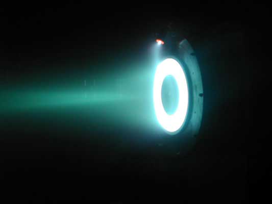
File:HallThruster 2.jpg

2 kW Hall thruster in operation as part of the Hall Thruster Experiment at the Princeton Plasma Physics Laboratory.

History

Hall thrusters were studied independently in the US and the USSR in the 1950s and '60s. However, the concept of a Hall thruster was only developed into an efficient propulsion device in the former Soviet Union, whereas in the US, scientists focused instead on developing gridded ion thrusters.

Two types of Hall thrusters were developed in the Soviet Union:

  • Thrusters with wide acceleration zone, SPT (Stationary Plasma Thruster) at Design Bureau Fakel.
  • Thrusters with narrow acceleration zone, TAL (Thruster with Anode Layer), at the Central Research Institute for Machine Building (TsNIIMASH).
  File:Russian stationary plasma thrusters.jpg                                Soviet and Russian SPT Thrusters                                  The common SPT design was largely the work of A. I. Morozov. The first SPT to operate in space, an SPT-50 launched on the Soviet Meteor spacecraft, was launched December 1971. They were mainly used for satellite stabilization in North-South and in East-West directions. Since then until the late 1990s 118 SPT engines completed their mission and some 50 continued to be operated. Thrust of the first generation of SPT engines, SPT-50 and SPT-60 was 20 and 30 mN respectively. In 1982 SPT-70 and SPT-100 were introduced, their thrusts being 40 and 83 mN, respectively. In the post-Soviet Russia high-power (a few kilowatts) SPT-140, SPT-160, SPT-200, T-160 and low-power (less than 500 W) SPT-35 were introduced.   Soviet and Russian TAL-type thrusters include the D-38,D-55, D-80,and D-100.   Soviet-built thrusters were introduced to the West in 1992 after a team of electric propulsion specialists from NASA's Jet Propulsion Laboratory and Glenn Research Center, under the support of the Ballistic Missile Defense Organization, visited Soviet laboratories and experimentally evaluated the SPT-100 (i.e., a 100 mm diameter SPT thruster).   Over 200 Hall thrusters have been flown on Soviet/Russian satellites in the past thirty years. No failures of a Hall thruster has ever occurred on orbit. Hall thruster continue to be used on Russian spacecraft and have also flown on European and American spacecraft. Space Systems/Loral, an American commercial satellite manufacturer, now flies Fakel SPT-100's on their GEO communications spacecraft. Since their introduction to the west in the early 1990's, Hall thrusters have been the subject of a large number of research efforts throughout the United States, France, Italy, Japan, and Russian (with many smaller efforts scattered in various countries across the globe). Hall thruster research in the US is conducted at several government laboratories, universities and private companies. Government centers include NASA's Jet Propulsion Laboratory, NASA's Glenn Research Center and the Air Force Research Laboratory (Edwards AFB, CA). Universities include the University of Michigan, Stanford, MIT, Princeton, Michigan Tech, and Georgia Tech. A considerable amount of development is being conducted in industry, such as Aerojet and Busek Co. in the USA, SNECMA in France and Alta in Italy.   The first use of Hall thrusters outside of Earth's orbit was on the European Space Agency (ESA) lunar mission SMART-1 in 2003. Hall thrusters were first demonstrated on a western satellite on the Naval Research Laboratory (NRL) STEX spacecraft, which flew the Russian D-55. The first American Hall thruster to fly in space was the Busek BHT-200 on TacSat-2 technology demonstration spacecraft. Aerojet has flight qualified the BPT-4000, which will first fly when the Advanced EHF military spacecraft is launched. Several countries worldwide continue efforts to qualify Hall thruster technology for commercial uses.   Operation   The essential working principle of the Hall thruster is that it uses an electrostatic potential to accelerate ions up to high speeds. In a Hall thruster the attractive negative charge is provided by an electron plasma at the open end of the thruster instead of a grid. A radial magnetic field of a few tens of milliteslas is used to hold the electrons in place, where the combination of the magnetic field and an attraction to the anode force a fast circulating electron current around the axis of the thruster and only a slow axial drift towards the anode occurs.  
         Hall Thrusters are Largely Axially Symmetric           
This is a cross-section containing that axis.
A schematic of a Hall thruster is shown in the image to the right. An electric potential on the order of 300 volts is applied between the anode and cathode.

The central spike forms one pole of an electromagnet and is surrounded by an annular space and around that is the other pole of the electromagnet, with a radial magnetic field in-between.

The propellant, such as xenon gas is fed through the anode, which has numerous small holes in it to act as a gas distributor. Xenon propellant is used because of its high molecular weight and low ionization potential. As the neutral xenon atoms diffuse into the channel of the thruster, they are ionized by collisions with high energy circulating electrons (10–20 eV or 100,000 to 250,000 °C). Once ionised the xenon ions typically have a charge of +1 though a small fraction (~10%) are +2.

The xenon ions are then accelerated by the electric field between the anode and the cathode. The ions quickly reach speeds of around 15,000 m/s for a specific impulse of 1,500 seconds (15 kN·s/kg). Upon exiting however, the ions pull an equal number of electrons with them, creating a plume with no net charge.

The axial magnetic field is designed to be strong enough to substantially deflect the low-mass electrons, but not the high-mass ions which have a much larger gyroradius and are hardly impeded. The majority of electrons are thus stuck orbiting in the region of high radial magnetic field near the thruster exit plane, trapped in E×B (axial electric field and radial magnetic field). This orbital rotation of the electrons is a circulating Hall current and it is from this that the Hall thruster gets its name. Collisions and instabilities allow some of the electrons to be freed from the magnetic field and they drift towards the anode.

About 30% of the discharge current is an electron current which does not produce thrust, which limits the energetic efficiency of the thruster; the other 70% of the current is in the ions. Because the majority of electrons are trapped in the Hall current, they have a long residence time inside the thruster and are able to ionize almost all (~90%) of the xenon propellant. The ionization efficiency of the thruster is thus around 90%, while the discharge current efficiency is around 70% for a combined thruster efficiency of around 63% (= 90% × 70%).

The magnetic field thus ensures that the discharge power predominately goes into accelerating the xenon propellant and not the electrons, and the thruster turns out to be reasonably efficient.

Compared to chemical rockets the thrust is very small, on the order of 83 mN for a typical thruster operating at 300 V, 1.5 kW. For comparison, the weight of a coin like the U.S. quarter or a 20-cent Euro coin is approximately 60 mN.

However, Hall thrusters operate at the high specific impulses that is achieved with ion thrusters. One particular advantage of Hall thrusters, as compared to an ion thruster, is that the generation and acceleration of the ions takes place in a quasi-neutral plasma and so there is no Child-Langmuir charge (space charge) saturated current limitation on the thrust density, and thus thrust is high for electrically accelerated thrusters.

Another advantage is that these thrusters can use a wider variety of propellants supplied to the anode, even oxygen, although something easily ionised is needed at the cathode. One propellant that is starting to be used is liquid bismuth due to its low cost, high atomic mass and low partial pressure.

Applications


Hall thrusters have been flying in space since December 1971 when the Soviets launched an SPT-50 on the Meteor satellite. Over 240 thrusters have flown in space since that time with a 100% success rate. Hall thrusters are now routinely flown on commercial GEO communications satellite where they are used for orbit insertion and stationkeeping.

On October 23, 1998, the first Hall thruster to fly on a western satellite was the Russian D-55 built by TsNIIMASH on the NRO's STEX spacecraft. On September 28, 2003, the first Hall thruster used outside of geosynchronous Earth orbit began as the European Space Agency's SMART-1 spacecraft started its journey to the moon using a Snecma PPS-1350.

The solar electric propulsion system of the European Space Agency's SMART-1 spacecraft used a Snecma PPS-1350-G Hall thruster. SMART-1 was a technology demonstration mission that orbited the moon. The use of the PPS-1350-G was the first use of a Hall thruster outside of geosynchronous earth orbit (GEO). Unlike most Hall thruster propulsion systems used in commercial applications, the Hall thruster on SMART-1 could be throttled over a range of power, specific impulse, and thrust:

  • Discharge Power: 0.46-1.19 kW
  • Specific Impulse: 1100-1600 s
  • Thrust: 30-70 mN
  In 2005, SMART-1 exhausted its xenon supply after flawlessly operating the thruster and establishing new records for Hall thruster operation in space.  
  • Thruster operating time: 5000 h
  • Xenon throughput: 82 kg
  • Total Impulse: 1.1 MN-s
  • Total ΔV: 3.9 km/s
  In parallel to the flight demonstration, a qualification model (QM) PPS-1350-G has also undergone wear testing on the ground. Through 2007, the QM model has demonstrated:  
  • Thruster operating time: 10,500 h
  • Total impulse: 3.39 MN-s
  • Start/Stop Cycles: 7309
  Hall-Effect Thruster Utilizing Bismuth as Propellant   A laboratory-model Hall-effect spacecraft thruster was developed that utilizes bismuth as the propellant. Xenon was used in most prior Hall-effect thrusters. Bismuth is an attractive alternative because it has a larger atomic mass, a larger electron- impact- ionization cross-section, and is cheaper and more plentiful.   The design of this thruster includes multiple temperature-control zones and other features that reduce parasitic power losses. Liquid bismuth (which melts at a temperature of 271°C) is supplied by a temperature-controlled reservoir to a vaporizer. The vaporizer exhausts to an anode/gas distributor inside a discharge channel that consists of a metal chamber upstream of ceramic exit rings. In the channel, bismuth ions are produced through an electron impact ionization process and accelerated as in other Hall-effect thrusters. The discharge region is heated by the discharge and an auxiliary anode heater, which is required to prevent bismuth condensation at low power levels and at thruster start-up. A xenon discharge is also used for preheating the discharge channel, but an anode heater could provide enough power to start the bismuth discharge directly.   Fuente: http://en.wikipedia.org/wiki/Hall_effect_thruster, http://www.techbriefs.com/links/3362 Nombre: Rodriguez B. Joiver I. Asignatura: CRF


Invite your mail contacts to join your friends list with Windows Live Spaces. It's easy! Try it!

Hall Effect Sensor

A Hall Effect Sensor is a transducer that varies its output voltage in response to changes in magnetic field. Hall sensors are used for proximity switching, positioning, speed detection, and current sensing applications.

In its simplest form, the sensor operates as an analogue transducer, directly returning a voltage. With a known magnetic field, its distance from the Hall plate can be determined. Using groups of sensors, the relative position of the magnet can be deduced.

Electricity carried through a conductor will produce a magnetic field that varies with current, and a Hall sensor can be used to measure the current without interrupting the circuit. Typically, the sensor is integrated with a wound core or permanent magnet that surrounds the conductor to be measured.

Frequently, a Hall sensor is combined with circuitry that allows the device to act in a digital (on/off) mode, and may be called a switch in this configuration. Commonly seen in industrial applications such as the pictured pneumatic cylinder, they are also used in consumer equipment; for example some computer printers use them to detect missing paper and open covers. When high reliability is required, they are used in keyboards.

A wheel topped with two magnets that pass by a Hall effect sensor

Hall sensors are commonly used to time the speed of wheels and shafts, such as for internal combustion engine ignition timing, tachometers and anti-lock braking systems.

They are used in brushless DC electric motors to detect the position of the permanent magnet. In the pictured wheel carrying two equally spaced magnets, the voltage from the sensor will peak twice for each revolution. This arrangement is commonly used to regulate the speed of disc drives.

Hall Probe

A hall probe contains an indium compound crystal such as indium antimonide, mounted on an aluminum backing plate, and encapsulated in the probe head. The plane of the crystal is perpendicular to the probe handle. Connecting leads from the crystal are brought down through the handle to the circuit box.

When the Hall Probe is held so that the magnetic field lines are passing at right angles through the sensor of the probe, the meter gives a reading of the value of magnetic flux density (B). A current is passed through the crystal which, when placed in a magnetic field has a "Hall Effect" voltage developed across it. The Hall Effect is seen when a conductor is passed through a uniform magnetic field. The natural electron drift of the charge carriers causes the magnetic field to apply a Lorentz force (the force exerted on a charged particle in an electromagnetic field) to these charge carriers. The result is what is seen as a charge separation, with a build up of either positive or negative charges on the bottom or on the top of the plate. The crystal measures 5 mm square. The probe handle, being made of a non-ferrous material, has no disturbing effect on the field.

A Hall Probe is sensitive enough to measure the Earth's magnetic field. It must be held so that the Earth's field lines are passing directly through it. It is then rotated quickly so the field lines pass through the sensor in the opposite direction. The change in the flux density reading is double the Earth's magnetic flux density. A hall probe must first be calibrated against a known value of magnetic field strength. For a solenoid the hall probe is placed in the center.

Hall Effect Sensor Interface

Hall effect sensor may require analog circuitry to be interfaced to microprocessors. These interfaces may include input diagnostics, fault protection for transient conditions and short/open circuit detection. It may also provide and monitor the current to the hall effect sensor itself. There are precision IC products available to handle these features. For example the Hall Effect Interface IC from Maxim Integrated Products is MAX9921.


Motor On A Hall Effect Switch

Motor on a Hall effect switch

This is a simple and probably the most reliable motor. You may take a look at how easy it is to assemble this motor from the kit.

In 1879 Edward Hall placed a thin layer of gold in a strong magnetic field. He connected a battery to the opposite sides of this film and measured the current flowing through it. He discovered that a small voltage appeared across this film. This voltage was proportional to the strength of magnetic field multiplied by the current. This effect bears his name.

For many years the Hall effect was not used in practical applications because the generated voltage in the gold film was extremely low. However, in the second half of the 20th century the mass production of semiconductor chips started. Chips based on the Hall effect became inexpensive and widely available.

The Hall effect IC (integrated circuit) is a very small chip which includes many transistors. It consists of a thin layer of silicon as a Hall generator (which works better than gold) and several transistor circuits: to amplify the Hall voltage to a necessary level; to trigger output voltage with its growth; and to provide stable work regardless of the power supply voltage changes. The picture below demonstrates the Hall effect IC:

Hall effect IC

The Hall effect IC is a solid state electronic device with no mechanical parts and therefore it is more reliable than a reed switch. To no surprise it is now the most widely used sensor in industrial brushless motors. Normally, however, they include a lot of other components. Stan designed a motor on a Hall effect switch with minimum parts based on the same unified mechanical design and it worked very well.

The Hall effect IC used in Kits 6 and 8 (or available as a separate part) is a unipolar switch. It turns on and off when the South pole of the magnet passes by its branded side. The North pole has no effect on it, unless it approaches from the back side of the Hall IC. This Hall effect IC has a built in voltage regulator and may work in the range from 4.5 to 24V. The Hall effect IC's included in the kit, however, were tested extensively; and it was found that most of them start working at 3V. This is a typical Hall effect IC shown from the branded side:


Hall effect IC

The Hall effect switch output current is not sufficient to power this motor, therefore it also requires a power transistor. You may find information on this component at How It Works: Reed Switch Motor With A Transistor.

This is how this motor works:


   1.   When magnet #1 gets close to the Hall IC, the sensor sends a signal to the base of the power transistor.
         The transistor opens, and allows a bigger collector current to flow through the electromagnet. The electromagnet pushes magnet #3 away.

Diagram #1


   2.  When the rotor spins away, magnet #1 stops affecting the Hall IC. Since the signal to the base of the power transistor has been removed, it is turned off.
        This disables the electromagnet.

Diagram #2

   3.   The rotor continues to spin due to inertia until magnet #2 moves into the working range of the Hall IC. The Hall IC sends a signal to the base of the transistor.
         The transistor opens, and allows a bigger collector current to flow through the electromagnet. The electromagnet pushes magnet #4 away.
         This process continues until the power is disconnected.

Diagram #3

This motor can be built from Kit #6. Complete instructions are provided. However, if you decide to design this motor yourself, you may order only the parts you need (Hall effect IC, PNP power transistor, magnet wire, magnets, heat sink).

Our experiments showed that the speed of this motor could be controlled by an extra magnet the same way the speed control unit works for the reed switch motors (see Assembly Instructions: Experimentation Kit #1 and How It Works: Reed Switch Motor). The magnetic field of the additional magnet placed near the Hall effect IC interacts with the magnetic field of the magnets on the rotor. As you move this additional magnet the combined magnetic field becomes stronger or weaker depending on the orientation of the speed control magnet. It affects the time the Hall sensor sends the signal to the transistor and therefore changes the motor speed. You may buy a speed control unit or just an additional magnet at our ordering page.


Fuente: http://en.wikipedia.org/wiki/Hall_probe#Hall_probe, http://www.simplemotor.com/hemotor.htm
Nombre: Rodriguez B. Joiver I.
Asignatura: CRF


Get news, entertainment and everything you care about at Live.com. Check it out!